At the beginning
There is a staircase in the house. It is very interesting to see many staircase renovation projects in the community. Not very busy recently, so I decided to use some open source hardware modules to transform the stairs at home and add some interactive functions. This project will not be particularly difficult, it takes me about an afternoon. If you also have a staircase in your house that needs to be renovated, I hope this sharing will help you.
STEP 1 - Preparing work
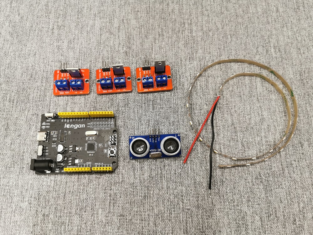
First, you need to prepare some materials, which include the following:
Electronic module
- A Longan Core board, or other Arduino development board
- Ultrasonic sensor for detecting whether someone has passed the stairs
- LED light bar
- MOS switch for controlling LED light bar
Consumables
- Wire
- DuPont Wire
- Header
Tool
- Soldering iron
- Wire stripper
- scissor
- Glue gun
STEP 2 - Connect the LED bar to the MOS switch and stick it under the stairs
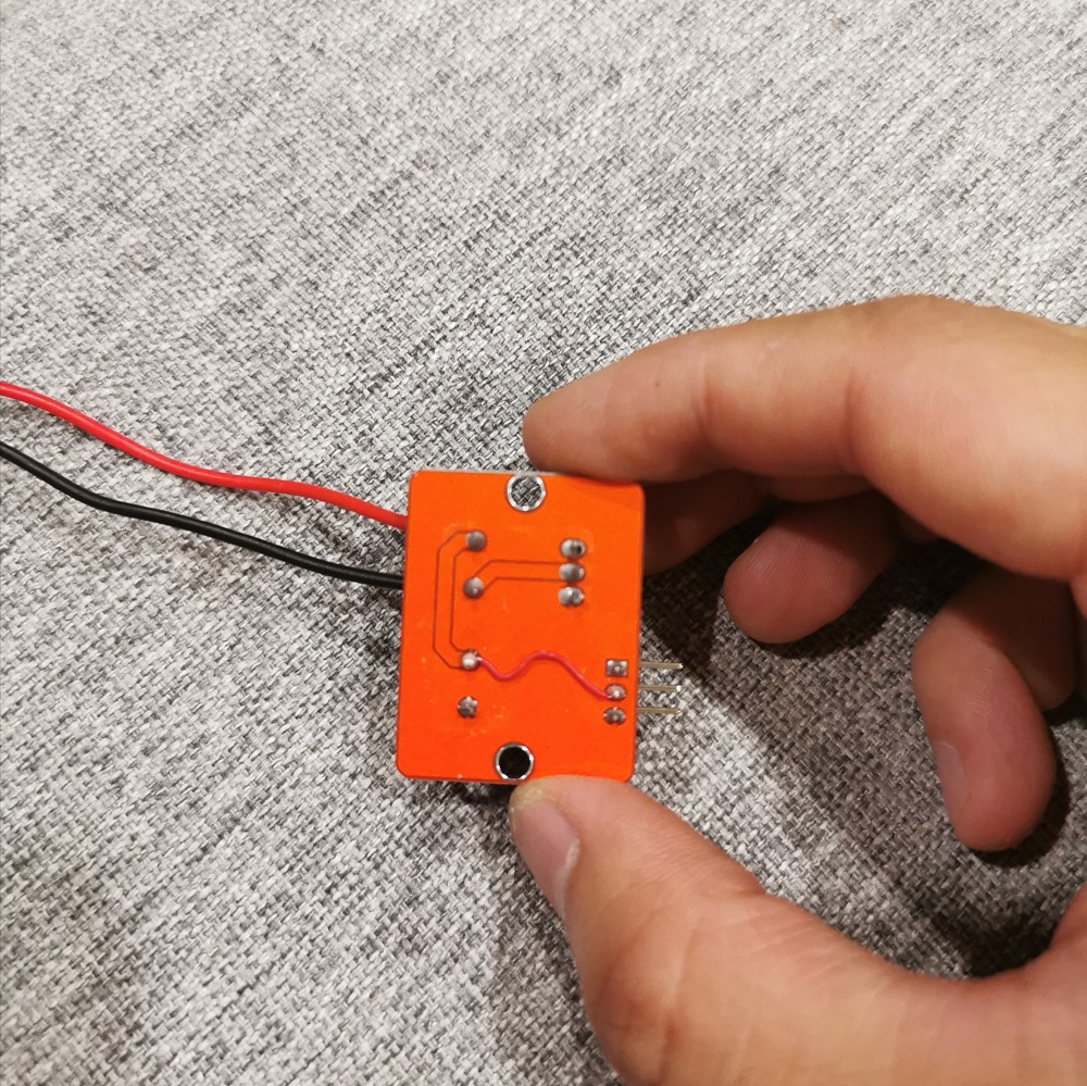
The function of the MOS switch is to amplify the current. As the Led bar need abouts 500mA, the IO port of the Arduino has no way to directly drive the LED light bar, and the IO drive capability of the Arduino can be utilized through the MOS switch.
The MOS switch has 3 interfaces, V + and V- are connected to the positive and negative poles of the LED bar, VIN and GND are connected to the positive and negative poles of the power supply. There is also a 3PIN control pins. SIG is connected to IO of Arduino, VCC is connected to 5V, and GND is connected to the negative pole of the power supply. Since the Arduino and the LED use the same 5V power supply, we connect the VIN of the MOS switch module to VCC through a wire, so that there is no need to connect the power supply twice.
Connect the positive and negative poles of the LED bar to V + and V-
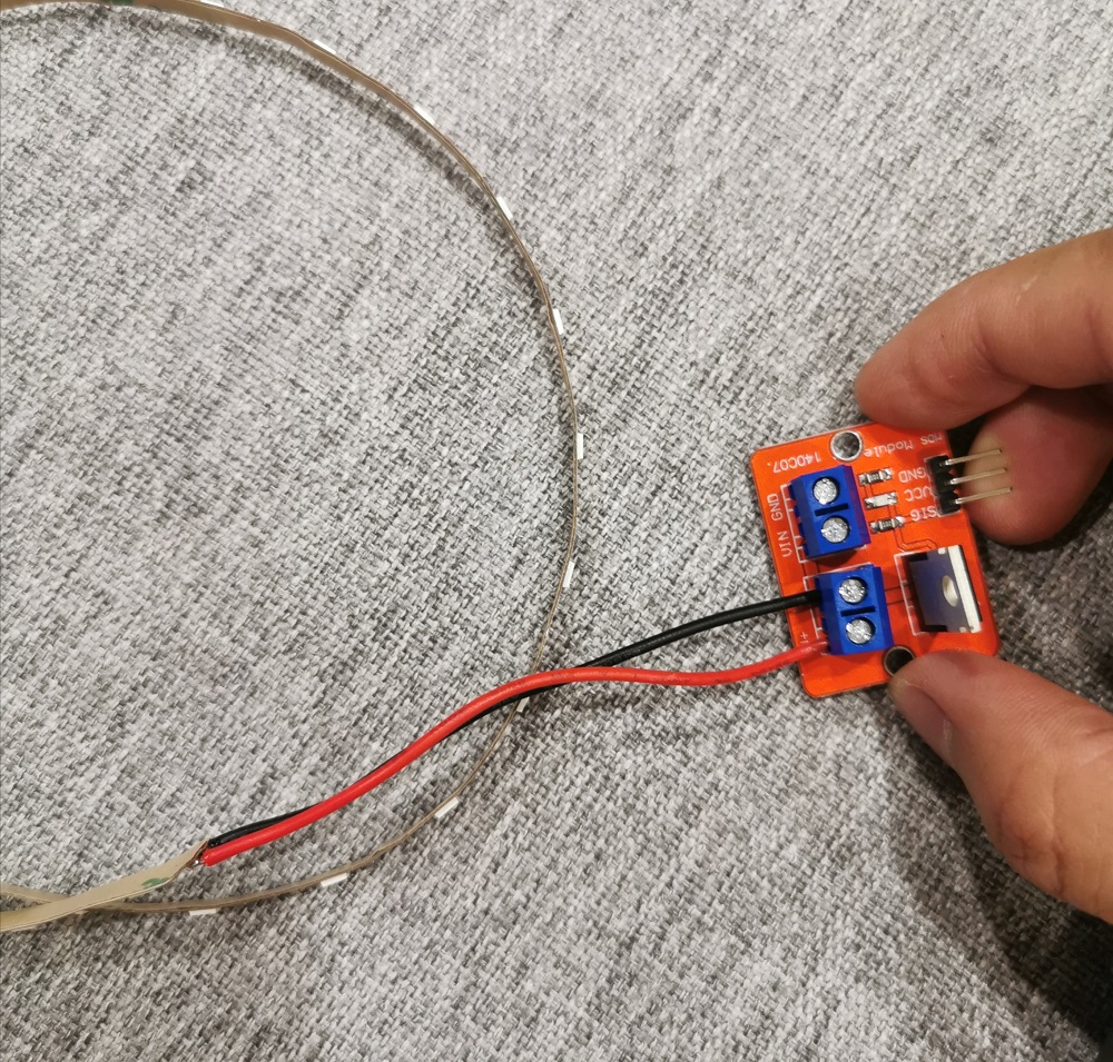
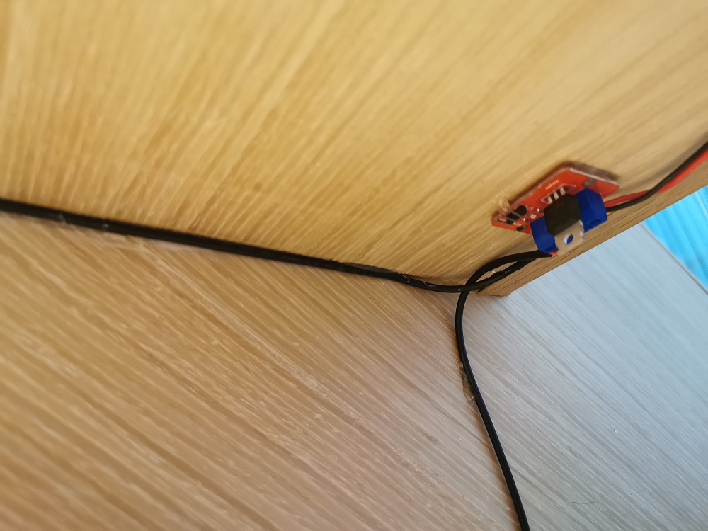
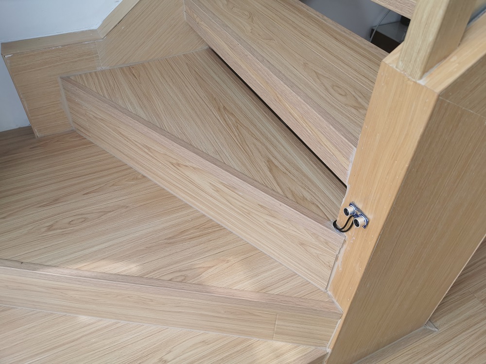
There is 3M tape on the back of the LED bar, which can be directly stuck under the stairs. The MOS switch can also be fixed under the stairs by glue gun.
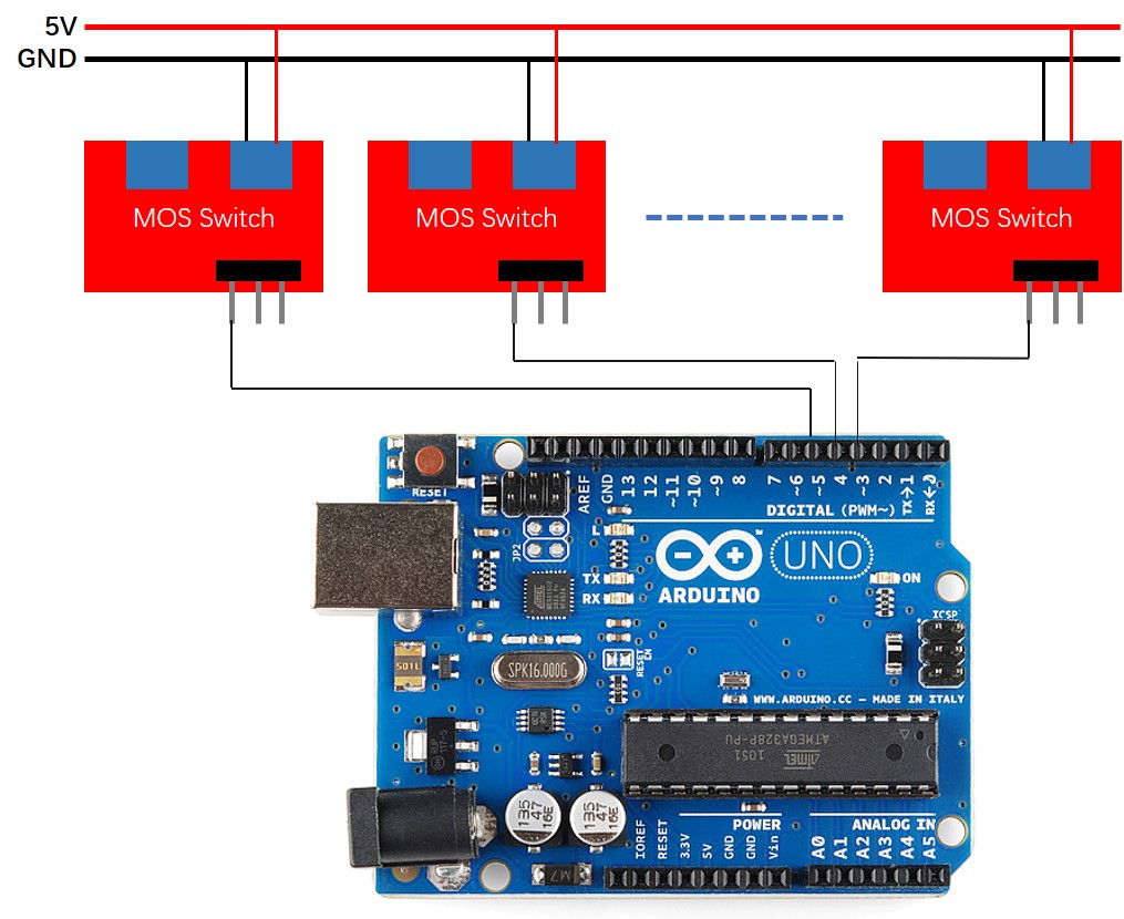
STEP 3 - Connect the power of all MOS switches together and fix to the stairs
In this step, you need to connect the power supplies of all MOS switches in parallel, and here you need some wires. The schematic diagram of the connection is as follows:
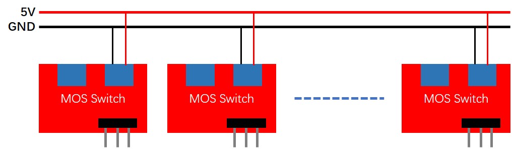
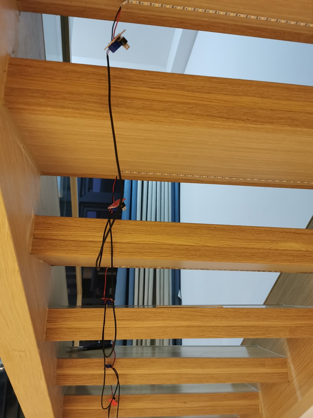
This is mainly a tedious job, after completion, as shown below:
STEP 4 - Fixed the ultrasonic sensor and Arduino
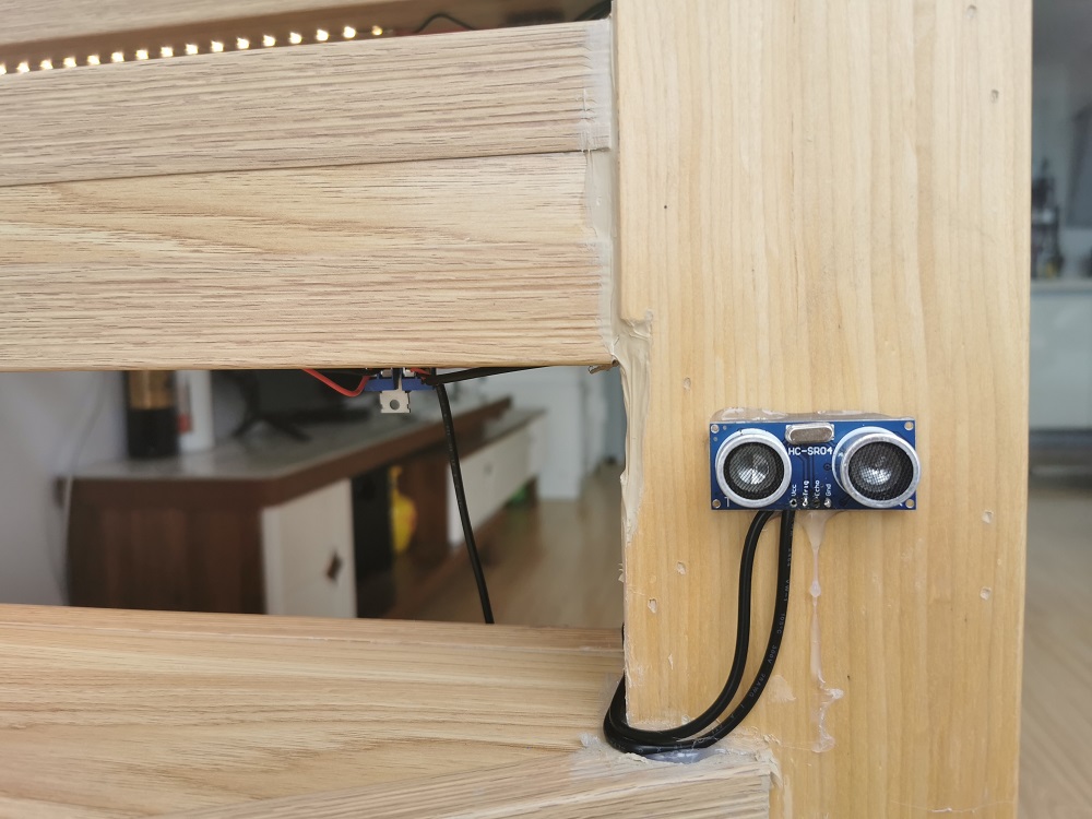
At the meantime, fix Arduino to backside of the stairs.
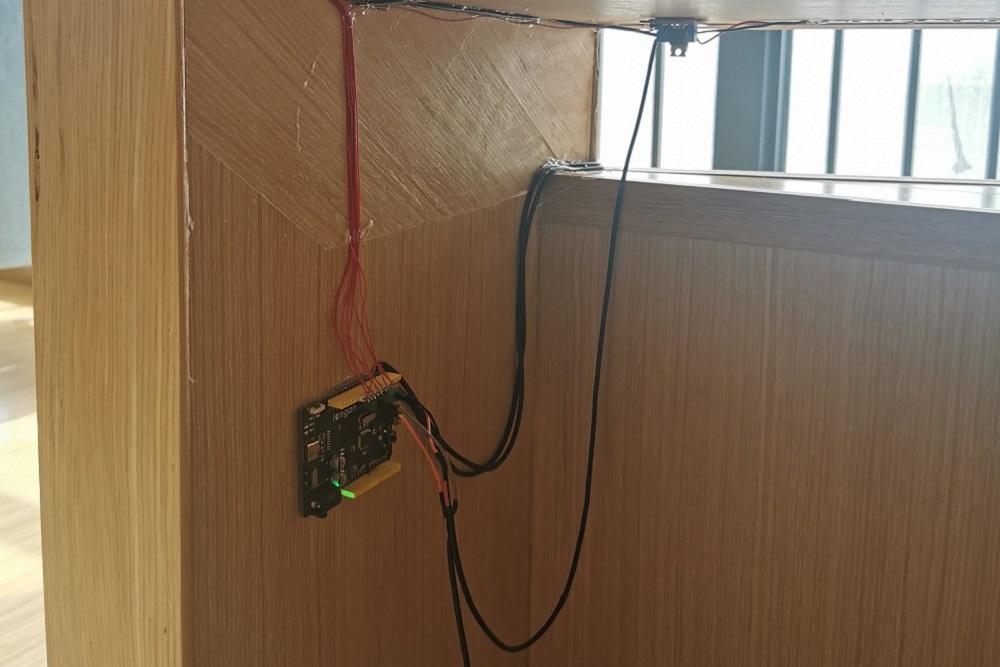
- VCC connect to 5V
- GND to GND
- Trig, this is the sending pin of ultrasonic sensor, connected to D2 of Arduino
- Echo, this is the receiving pin of ultrasonic sensor, connected to D3 of Arduino
STEP 5 - Connect the signal of the MOS switch to the Arduino IO
A total of 9 MOS switches are used in this project. We connected the SIG of 9 switches to D4 ~ D12 of Ardino. The schematic diagram is as follows:
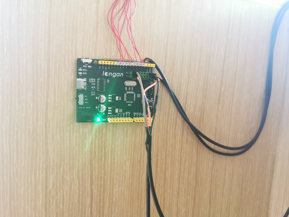
This is also a tedious job, which requires soldering and fixing a lot of wires and requires a little patience. The completion is as follows:
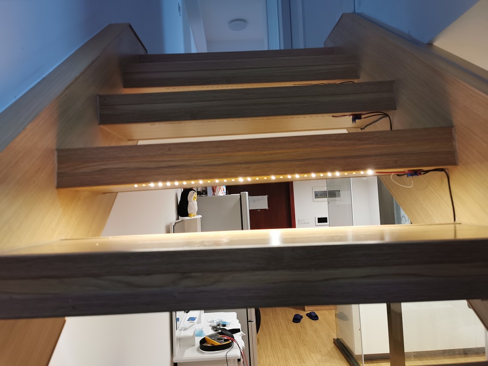
STEP 6 - Power-up test
Connect the two power cables connected to the MOS switch in STEP3 to 5V and GND of the Arduino.So far the most difficult work has been completed. We need to check whether there is a problem with the wiring. Open the Arduino IDE and write the D4-D12 pins to a HIGH level to see if all the LEDs work well. If some of them don't work, we need to check the wiring.If the wiring is well, we can start the interesting software work now.
STEP 7 - Programming with Arduino IDE
Here we use the famous Arduino IDE for programming.The ultrasonic sensor needs a library to drive, click to download.In this project, I simply wrote an example. When a person is detected, the light will slowly light up.Of course, you can add some interesting interactions according to your preferences.